| ZX Spectrum Backplane |
| MDFS::Info.Comp.Spectrum.Backplane | Search |
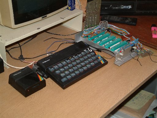
I could see that the biggest barrier to playing around with interfacing to the Spectrum was the potential to rapidly use a lot of expensive edge connectors and the inability to plug in more than one interface without lots of edge connector extenders. However, my father worked in the Medical Physics section of the local hospitals (he designed the first portable kidney dialysis machine). The hospital was chucking away a load of defunct electonic kit. The attraction to me was that it was all built on boards that plugged into a backplane.
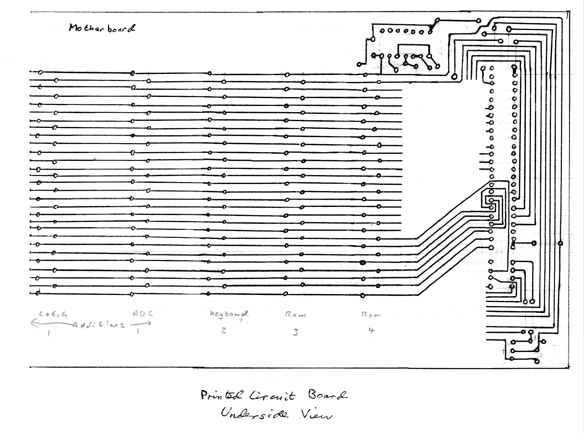
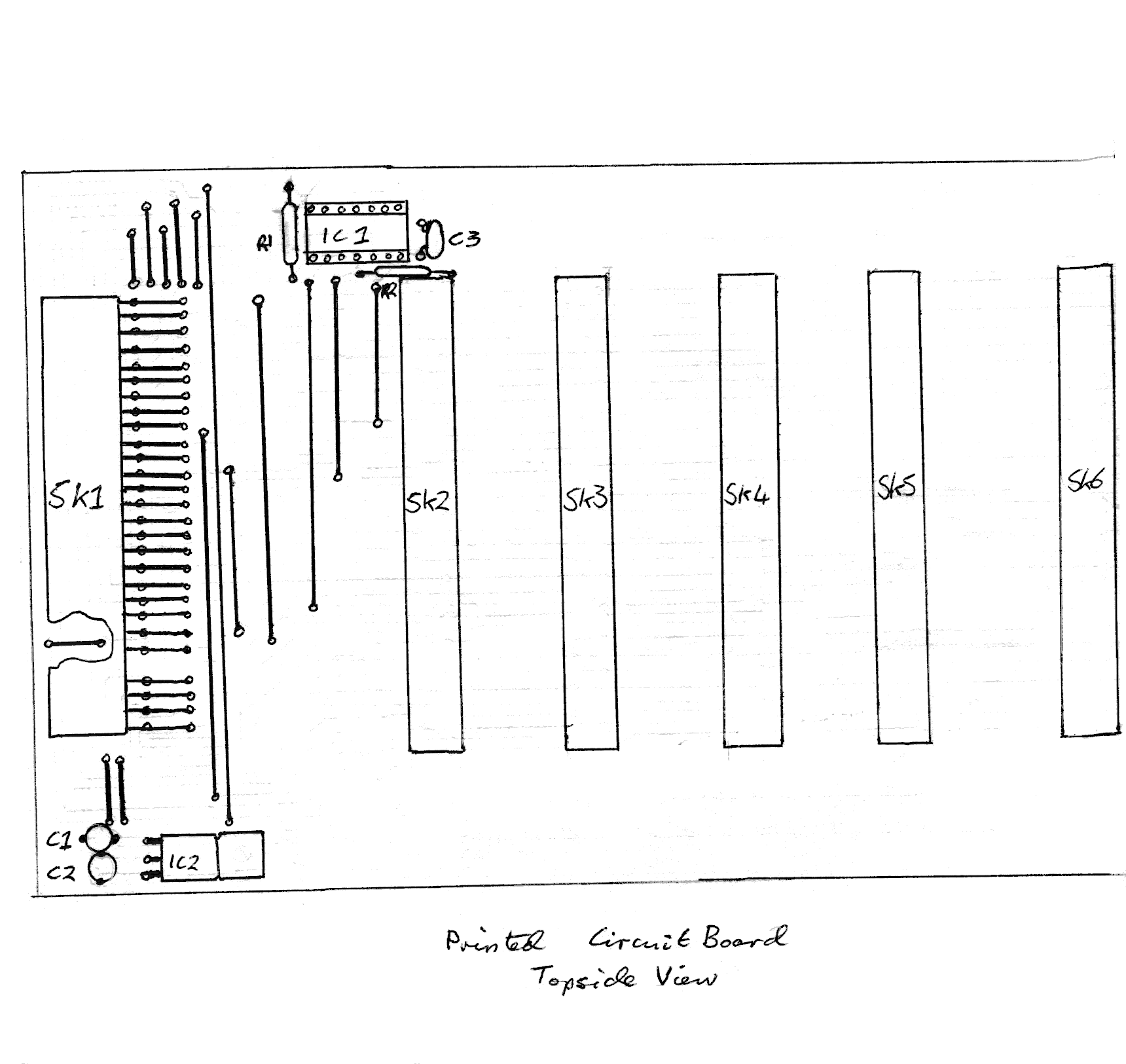
I salvaged a pile of these cards and backplane sockets, and during the summer of 1985 I built myself a backplane for the Spectrum, giving me the most useful expansion port signals in a more usable manner. I can't claim to be original in this, I'm sure I saw a picture of something similar which inspired me, probably the USP backplane.
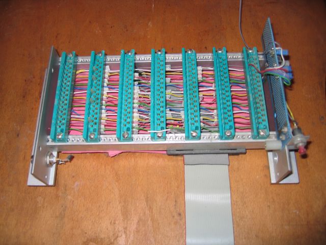
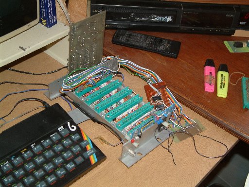 Seven-slot Spectrum backplane. Why seven? I suppose card zero is the control circuitry at the end. |
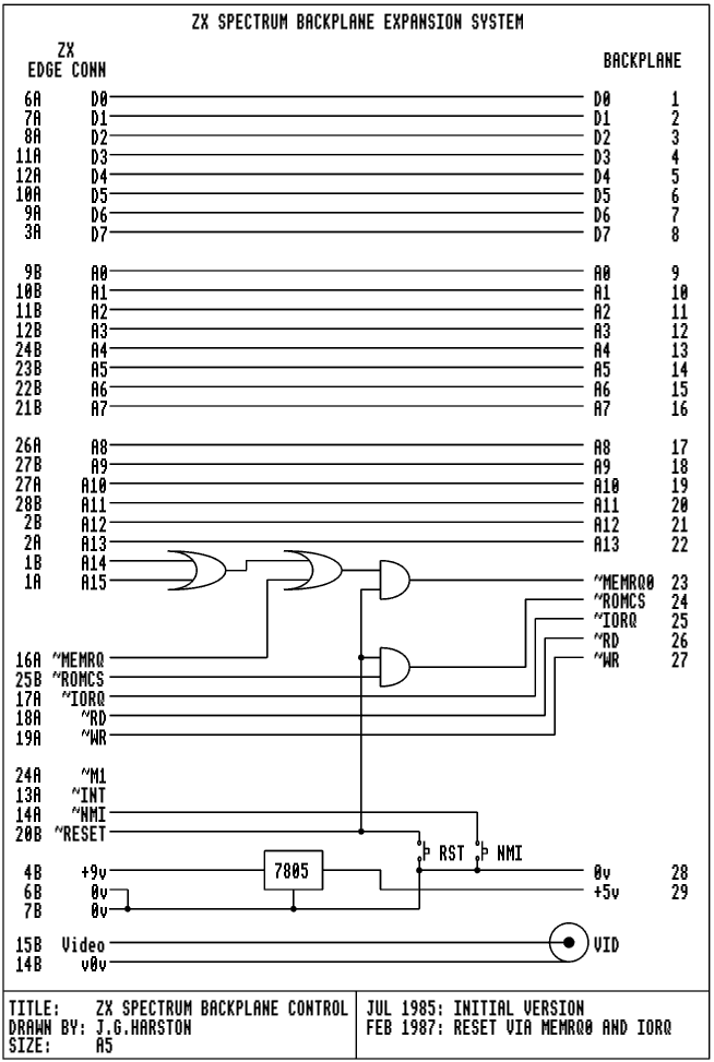
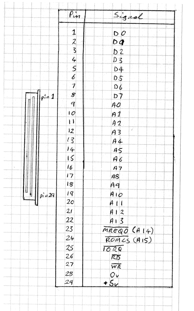
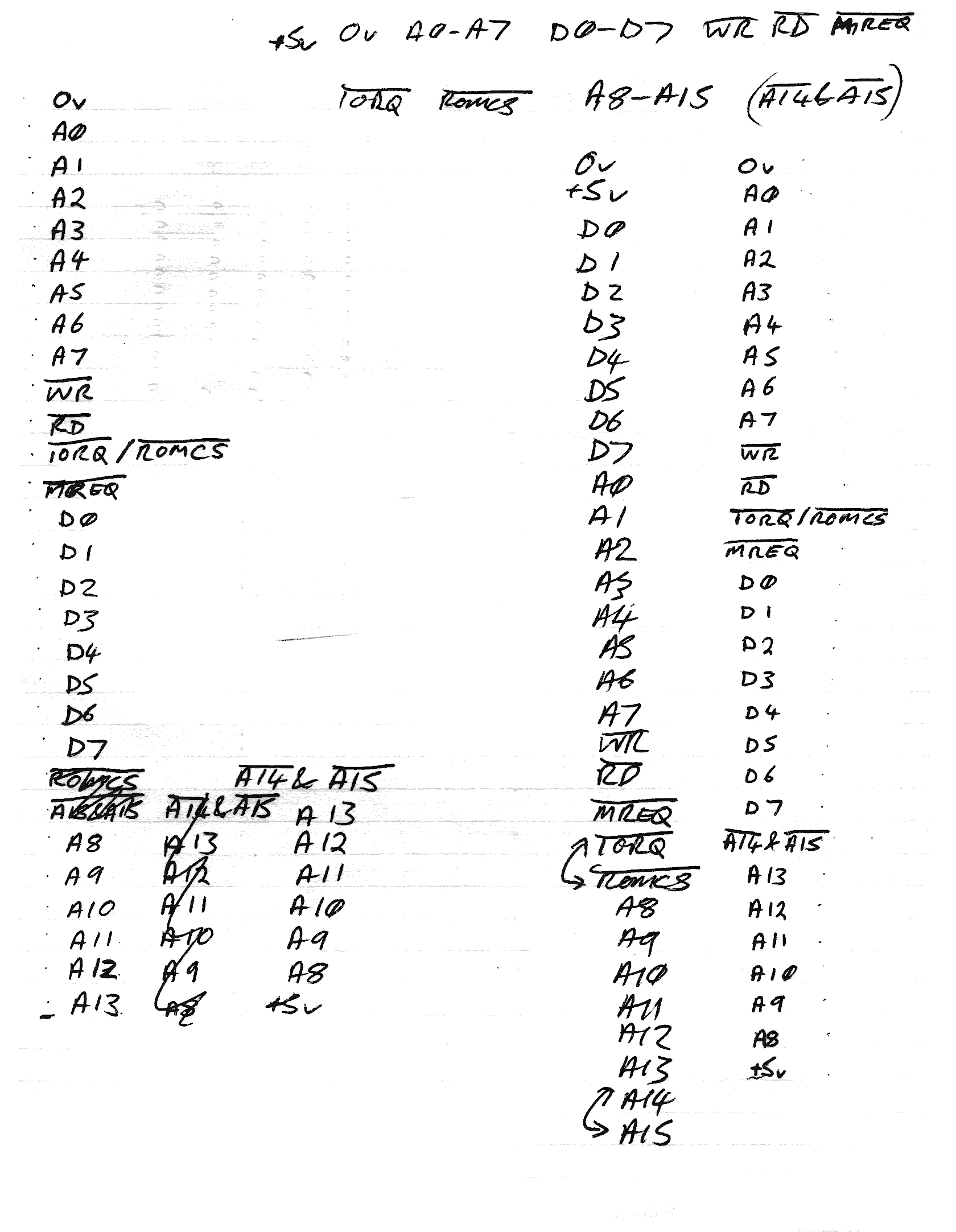
The card connectors only had 29 pins, so I had to carefully choose what signals I used. However, with careful design, I got all the signals I needed for the interfaces I designed and played with.
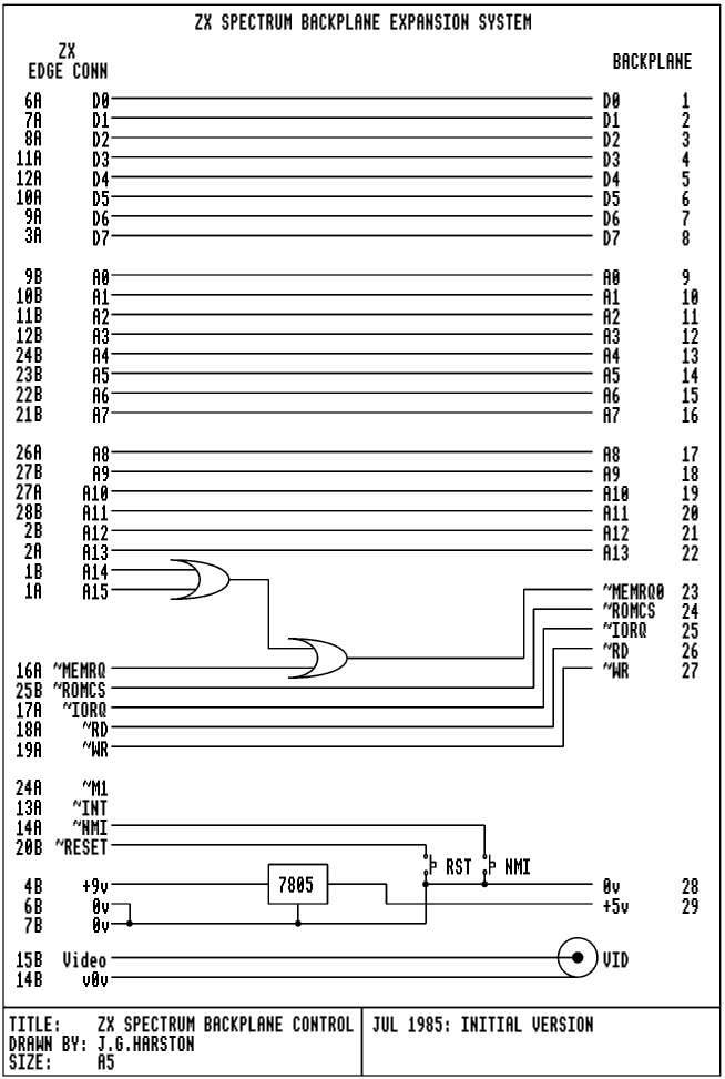
+5v, 0v, D0-D7, A0-A7, ~IORQ, ~RD and ~WR give enough signals to access I/O ports with 8-bit addressing, ignoring the upper byte. I wanted to experiment with paging over the Spectrum ROM, but there weren't enough pins left for A8-A15. However, combining A15, A14 and ~MEMRQ gives a ~MEMRQ0 signal active when accessing the bottom 16K of memory. Add on ~ROMCS and that's 29 pins!
| JGH SPECTRUM BACKPLANE SIGNALS | |||||||||
|---|---|---|---|---|---|---|---|---|---|
| DATA | ADDRESS LOW | ADDRESS HIGH | CONTROL | POWER | |||||
| 1 | D0 | 9 | A0 | 17 | A8 | 23 | ~MEMRQ0 | 28 | 0v |
| 2 | D1 | 10 | A1 | 18 | A9 | 24 | ~ROMCS | 29 | +5v |
| 3 | D2 | 11 | A2 | 19 | A10 | 25 | ~IORQ | ||
| 4 | D3 | 12 | A3 | 20 | A11 | 26 | ~RD | ||
| 5 | D4 | 13 | A4 | 21 | A12 | 27 | ~WR | ||
| 6 | D5 | 14 | A5 | 22 | A13 | ||||
| 7 | D6 | 15 | A6 | ||||||
| 8 | D7 | 16 | A7 | ||||||
The small amount of circuitry on the backplane also provided NMI and RESET buttons, and generated a regulated +5v supply for the backplane from the Spectrum's 9v supply rather than drawing more current from the Spectrum's +5v line. Additionally, the VIDEO signal is provided on a BNC socket to easily plug into a monitor. This is shown in the version 1 circuit diagram.
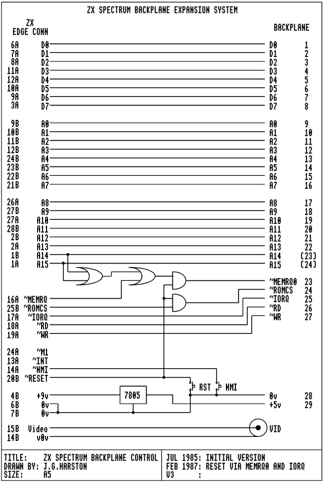
I later made two further modifications as shown in this
circuit diagram. This provided a RESET signal to the
cards. The way I did this was rather sneaky, as I had run out of pins!
Examining the signals I realised that ~MREQ (~MREQ0 at the card connector)
and ~IORQ could never both be active at the same time.
 So, I defined the signals on the card connector such that ~MREQ and ~IORQ
both being low indicated a RESET. Earlier cards worked fine as if either
~MREQ or ~IORQ were active without ~RD or ~WR being active, nothing
happened. Later cards that knew about the RESET state could create a ~RESET
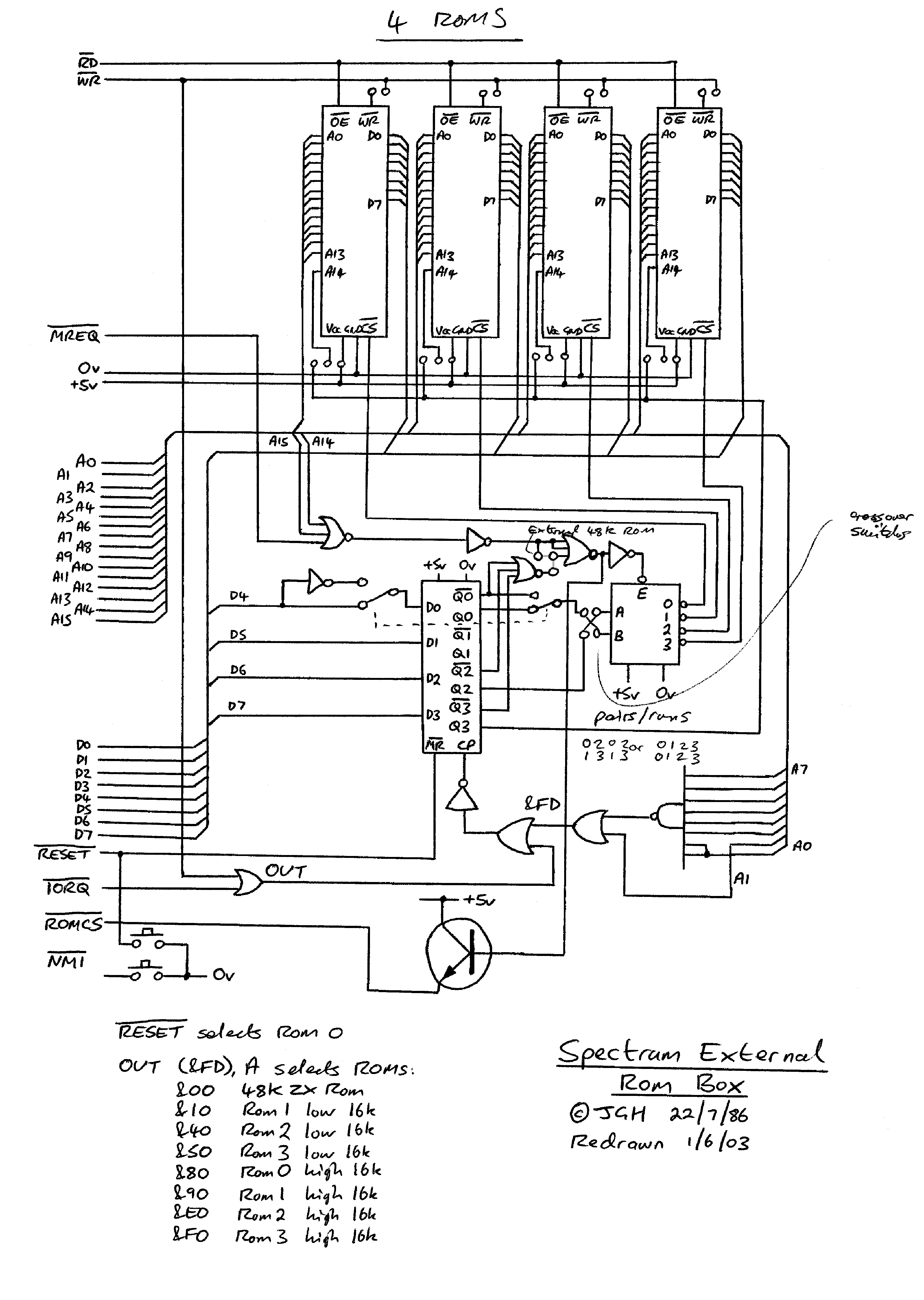
signal by ORing ~MREQ0 and ~IORQ together. I used this on the ROM card to clear the ROM latch on RESET.
So, I defined the signals on the card connector such that ~MREQ and ~IORQ
both being low indicated a RESET. Earlier cards worked fine as if either
~MREQ or ~IORQ were active without ~RD or ~WR being active, nothing
happened. Later cards that knew about the RESET state could create a ~RESET
signal by ORing ~MREQ0 and ~IORQ together. I used this on the ROM card to clear the ROM latch on RESET.
I ended up prototyping almost all my Spectrum add-on hardware with this backplane.
|
Spectrum backplane |
 Spectrum backplane |
 Close-up of the backplane |
|

 Authored by J.G.Harston